|
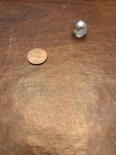
November 11, 2017 - The first step taken to begin the project was to decide what ball I am going to use. Since this will determine the scale of the machine, this was a high priority. I chose to use marbles which measure approximately .6 inches in diameter. On the right is a picture of one of the marbles with a penny for scale. For this size ball, the machine will be fairly small and it is possible that I will later decide to use bigger balls.
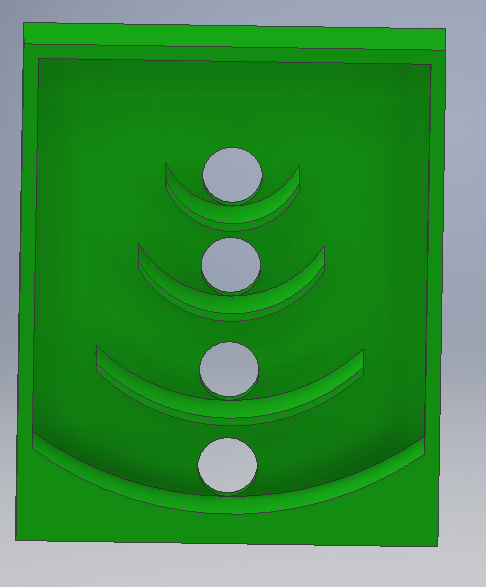
December 12th - The second step has been to begin modeling the machine. The first part completed was the head of the machine; where the balls go into the holes to score. The 3D model file of the machine is on the right. The part will be later changed to add electronics and interlocking tabs into it. This size increase could possibly require me to split the head into multiple printable parts, however this is my planned design for this part, which will be tested in the future.
January 8th - I have 3D modeled the ramp of the machine. This will connect to the head of the machine that I have already designed and will be the place where one starts to roll the ball. To make the ramp scaled properly to the head, I needed to make it into two pieces that could be printed separately, so I added holes and pegs to connect them. This ended up being an effective way to connect the pieces. On the right are pictures of the parts separated and a picture of the parts connecting.
January 12th- I have created most of the main code to run the machine. This part of the code is meant to keep track of score and the number of balls used. This will be done by adding the number of points up in a variable and adding up the number of times that the score was changed in another variable. The amount of points added depends on which sensor gives the input, since each hole has different point values. Later, I plan to add a part to the code that resets the score after 8 balls have been used, as well as a part to print the score and balls used on a LCD screen. On the right I have a picture of the code used as well as a wire diagram of the wiring used to test the code with my Arduino.
January 12th- Upon further consideration, I have decided to change the sensor used in the machine from a distance sensor to a switch. This will greatly reduce the project's cost and should reduce the amount of coding required significantly.
January 13th- I 3D printed a test of interlocking parts. After printing the parts, I learned that I should cut off one side of the tab to make a flat edge from the top to the bottom on one side. This allows the tab to move closer to the edge of the box it fits into. It also makes it easier to calculate the dimensions needed to make the edges of the connected parts flush. On the right is a slideshow showing the parts connecting in the 3D modeling software as well as a picture of them separated and connected in real life. After this test, I know that my idea of how to interlock the parts will work and I will begin to add the tabs to each of parts of the machine.
January 31st- Created the code to keep track of the number of balls and say game over after 8 are used on the lcd screen. The code was tested for errors and after minimal bug fixes, the code successfully worked. Now I am ready to combine this code with the code to keep track of score.
February 2nd - I have combined the code to keep track of the number of balls used with the code to keep track of score. I also changed the code to print the total number of points onto the LCD screen. However, the code does not work as of now and will require bug fixes.
February 5th -After bug fixes the code is now working. In this final stage, depending on which sensor recieves input, the score is changed accordingly to add a number of points (Currently 0,10,20 or 30) to the total. This is then printed on the LCD screen to see the number of points they have earned. The number of tries that the player has left is also printed, which reaches 0 after 8 tries; at which point the LCD prints that the game is over and flashes the number of points the player has earned throughout the game. In the future, I will use this code and wiring in the machine to have a system of displaying score and tries left to the player.
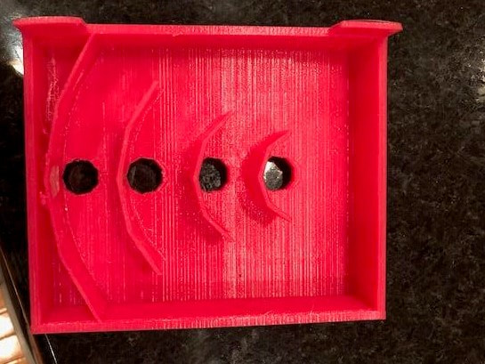
February 11th- After several tries I have gotten a prototype of the head of the machine 3D printed on my printer. The first few warped at the edges which led the print to slide off of the printing tray and fail. To fix this, I put duct tape on the printing tray where the main body of the print would be and added tabs to the side of the print. After this, the head finished successfully after many hours of printing.
February 15th- After further consideration, I have decided that 3D printing the ramp of the machine will not be the best option. I decided this because it will take a long time to print, and in order to reach the ramp size I need the parts would need to interlock and that would be difficult to print perfectly to avoid a ledge between the parts. This would also most likely eliminate the need for interlocking parts given that the head is small enough to be created in one print. For this reason, I have decided to use a foam board to create the ramp. Today I have bought the foam board I will use to create the machine.
February 23th- I have begun prototyping the dimensions that will be used in the final model. To do this, I used part of the foam board as a ramp and created a backboard to rest the head on. I used a clamp on the backboard to allow the angle of the head to be changed easily. To change the angle of the ramp, I stacked items found around my house to change the height at the back of the ramp. I also discovered that the 3D printed part of the ramp needed to have a different angle and to test the angle I used parts of the foam board to lift the back of it. Now that this is done, I have the dimensions I need for the main body of the final model. On the right are some pictures of the way that I prototyped the machine.
February 24th- After further thought and testing, I have realized that the limit switches I am using to keep the score and tries left are too stiff to detect the marbles dropping. To fix this problem, I added a piece of foam board to the end of them as well as a penny. This added weight makes them detect the falling marble, but does not prevent the switch from working. For this to work, I will need the balls to fall; and would be difficult to create a guide tube for them to fall. However, the balls always seem to fall in the same place for the hole that they go into, which would make registering them after a free fall without a guide tube a valid option. However to do this, I will need to determine where they fall which I will do using carbon paper.
February 25th- After prototyping the machine, the head seems to require some changes. These include making the holes bigger since the balls did not always go through them cleanly, lowering the top hole to meet the edge below it and filling in the gap below the first ledge to prevent balls from going in there. I also removed the tabs given that the head will print on its back this time; so they are not needed. Now that these changes are made, the final copy of the head is ready to be printed.
February 27th- After testing with carbon paper, I have determined that the balls do not fall consistently enough to free-fall onto the sensors. For this reason, I have added paper tubes to the back of the final head to direct the balls almost directly onto the sensors. I have also created an array to hold the sensors in the correct place to properly register the balls.
March 2nd- I have completed the design of the final model of the machine. This final model will cover the Arduino microcontroller, the sensors and have a ball retrieval system. I will begin construction over this weekend.
March 4th- Most of the construction is done, the outline of the structure is made and the head and sensors are in the correct place. This provides an outline to add the Arduino shelf and the ball retrieval system.
|

|
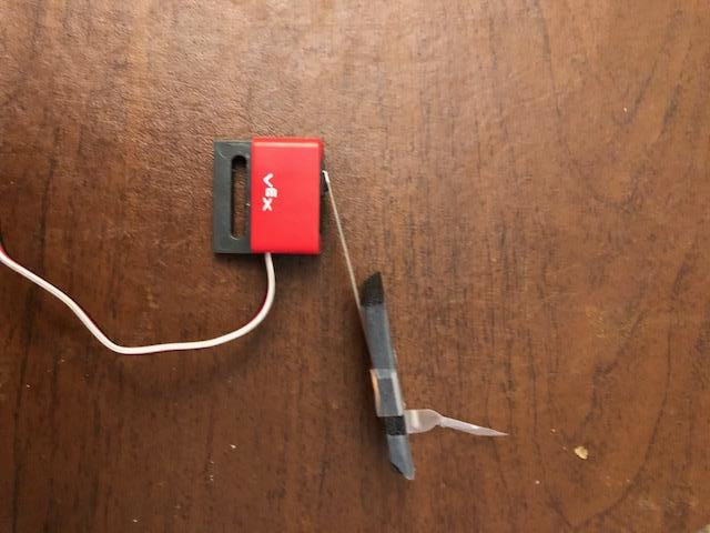
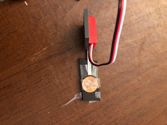
Photo used under Creative Commons from jasonwoodhead23
